Some of Our Projects
Project Title: Emergency Diesel Generator - Hinkley Point C Nuclear Project
Client: Bouygue Energy and Services in Conjunction with EDF Energy - Hinkley Point C Nuclear Project
Location: United Kingdom
Project Status: Ongoing
Technical review of Gen-set hydraulic calculation models
A multi-million pound project for the supply, installation and commissioning of the Emergency Diesel Generators (EDG) and all of their auxiliary systems for the new nuclear power station at Hinkley Point C.
Fedem Engineering was commissioned to provide technical review, result interpretation, solution recommendation and model verification of Gen-set hydraulic model to ensure they met client's technical and quality requirements. The models include:
-
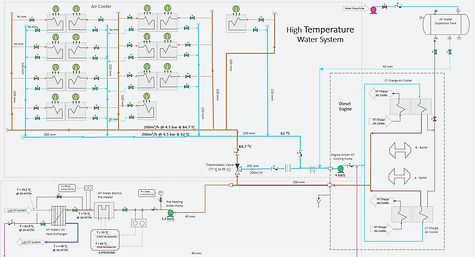
High Temperature (HT) cooling and Pre-heating System
-
Low Temperature (LT) cooling system
-
Fuel Oil System
-
Lubrication Oil System
-
Air Starting System
Steady State Hydraulic Simulation of Fuel Oil and Compressed Air System
Fedem Engineering developed fuel oil and compressed air simulation models to size pipes, pumps, orifice plates, evaluate heat transfer in pipes & heat exchanger, and determine pressure drop for the Gen-set systems using AFT Arrow and AFT Fathom fluid dynamic simulation software.
Transient Analysis of Pump Start-up with Event Transients using AFT Impulse
Fedem Engineering looks at various pump start-up cases for the HT and LT cooling system. The objective was to use transient analysis to determine the maximum and minimum pressure in the system to assess whether the system cavitates or experiences sub-atmospheric pressure during pump start-up and shutdown.
Transient Analysis of Valve Closure and Pump Trip with Accumulator using AFT Impulse
Fedem Engineering evaluated the effect of adding a gas expansion tank to cooling system network to minimize down surge due to the pump trip to keep all pressures above atmospheric. Various discharge valve closure times were analyzed to examine the impact on the system when the valves close quickly enough to prevent reverse rotation at the pump, and when the valves do not close completely before reverse rotation occurs in the pump.
P&IDs Review and Update
Fedem Engineering assisted in checking, red-marking, recommending and updating clients P&IDs using AutoCAD tools, ensuring client's technical and quality requirements are met.
Help new hires get acquainted with AFT Software Packages
Other engineering services
Development of EDG system list such as line list, valve list, instrument list and Equipment list. The line list provides a list of all the schematic piping that are included in the P&ID diagram and helps to establish the link between individual piping in the P&ID and isometric/spool drawing.


Project Title: BOS Gas Recovery Plant Optimisation
Client: Flex Process Consultant in Conjunction with Tata Steel
Location: Port Talbot, UK
Project Status: Completed
Relief and Flare Study - BOS Gas Recovery
The BOS plant is a multimillion pounds project designed to recover and reuse high calorific value carbon monoxide as a source of energy for on-site power plants.
Fedem Engineering was commissioned to provide process engineering solutions, including:
-
Performed pressure relief studies to validate adequacy of existing PRVs size and associated piping and equipment for the credible worst cases, in support of safety case justification.
-
Identification of relief cases and generation of PRV calculations with reference to API 520, API 521 and API 526.
-
Used Hysys simulation software to generate stream conditions, properties and composition at relieving conditions
-
Red mark-up of master P&IDs, working with CAD technician to revise P&IDs to as-built status
Relief and Flare Study - Converter Off-Gas Cooling and Steam Generation System
Fedem Engineering provided the following services:
-
Performed a pressure relief study and calculation to independently check the relief rationale for the existing steam system and that the PSV and pipework are adequately sized.
-
Updated existing P&IDs, sequence of operation, alarm and setpoint list, process logic and plant control philosophy documents to demonstrate compliance with regulation
-
Participated in HAZOP Studies; prepared and implemented responses to HAZOP actions and issues arising
Dynamic Simulation of Steam Drum Using Dynsim simulation software
Fedem Engineering developed dynamic simulation of steam drum to aid in understanding and optimisation of the steam drum three-element control strategy used to control steam drum level.
Dynamic Simulation of Compressor Train using Dynsim simulation software
Fedem Engineering developed dynamic simulation to provide an insight into compressor surge behaviour and other transient operations. The transient operations are blockage of valve downstream to the compressor, change in the feed temperature and loss of cooling water.
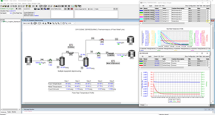
KO Drum Depressuring using Dynsim simulation
Fedem Engineering performed Thermal Analysis of flare relief lines to realistically calculate the piping mean metal temperature during relief and avoid unnecessary relief pipe replacement, or redesign.


Project Title: Factory Acceptance Test Facility and BWT Design
Client: Coldharbour Marine Ltd (CHM)
Location: Nottingham, United Kingdom
Project Status: Completed
Cooling System Investigation, Selection & Design
A multimillion pounds project designed to allow for the Factory Acceptance Testing of all Inert Gas Generators ranging from 500Nm3/hr (0.5MW) IGG to 6000Nm3/hr (6MW) IGG. Fedem Consulting was commissioned to carry out FEED, select and design an evaporative cooling system to provide cooling requirement for the Inert Gas Generator:
Fedem Engineering had to consider how to dissipate the process heat generated by the Inert Gas Generator (IGG) in a Factory Test environment when the normal "in-service" route of seawater cooling was unavailable.
The problem was defined as requiring an environmentally acceptable, cost effective and reliable method to achieving a combustion chamber cooling water temperature difference of 10 deg C.
A literature review of the two main types of cooling systems; closed circuit cooling system and open circuit cooling system was conducted. We then went on to select and install the later, an open circuit evaporative cooling system due to its ability to achieve lower temperature approach; low capital and operating cost as well as lower power consumption.
Piping and Instrumental Diagram (P&ID), control philosophy, alarm and setpoint list and sequence chart for the FAT facility cooling system was developed; and aided in the commissioning process alongside technicians.
The cooling system has been commissioned and currently provides cooling requirements for the full range of manufactured IGG's during Factory Acceptance Testing. In addition, it provided cooling requirements for IGG plant during CHM successful Lloyds Type Approval Test.
Root Cause Analysis Investigation and Development of Soft-start Sequence of Operation
During FAT Testing, whilst performing first ignition test, CHM IGG experienced an explosion which led to the mechanical failure of combustion chamber flexible hose pipework.
To mitigate the risk of further avoidable explosion, Fedem Consulting investigated the root cause of the explosion and persuaded senior management to implement a soft-start/stop sequence of operation. This saw the plant starting at a low fuel flow rate and low combustion chamber pressure, with vent valve set at 80% open position to provide adequate deflagration venting during ignition. The mode of operation was in accordance with recommendations set out in BS EN 416-1 and NFPA 69. The soft start/stop procedure was adopted, and various successful experimental test runs were carried out without further incident.
Optimisation of IGG Combustion Chamber Pressure Requirement
CHM IGG was designed to maintain an operating combustion chamber pressure of 200mbar. On-board ship, this pressure is achieved and maintained via a modulating valve located on the IGG vent line and a 2m deep barometric leg at the drain line of the IGG ensures a liquid seal is maintained in the combustion chamber, thus ensuring that no gas leaves the IGG via the water drain line.
As CHM FAT facility does not allow for a conventional barometric leg due to height restrictions and limitation in the facility layout, I was tasked to come up with a solution that would provide a barometric leg functionality.
Fedem Engineering researched several efficient and cost-effective options - using control valve or restriction orifice plate. The research revealed that using a restriction orifice would solve the problem. The desired orifice nozzle size was then determined and specification sheet prepared. Overall control philosophy and sequence of operation for the new solution was also prepared.
The use of restriction orifice plate has now been adopted by CHM as an alternative design option for retrofit vessels, as it provided barometric leg functionality during our successful Lloyds Register type approval test and subsequent factory acceptance test exercises.
Inert Gas Dispersion Modeling using Flaresim
To address the concern of local authority and to demonstrate that the emission of combustion product
(inert gas) from CHM plant was within the EU recommended Environmental Assessment Level (EAL), Fedem Engineering was commissioned to undertake an Air Quality Impact Assessment using dispersion modeling.
The assessment was used in support of planning application from the local authority. In the project, sets of combustion calculations were produced for the dispersion modelling. The calculations show how different anticipated combustion scenarios (complete and incomplete combustion) affects the formation of soot and NOx (air pollutants) during combustion process.
Hydraulic Design of a cooling water systems using Pipenet
The cooling water system has three heat exchangers in parallel, with a single pump driving the system. Fedem consulting was commissioned to model a closed-loop system using Pipenet software. The objective was to perform pipe-sizing calculation, select an appropriate pump and balance the system using orifice plates in order to eliminate excess flow.
Project Title: IGG Automation Project


Client: Coldharbour Marine Ltd (CHM)
Location: Nottingham, United Kingdom
Project Status: Completed
IGG Automation Project
This project was created to fully automate the Coldharbour Marine’s Inert Gas Generator. It involves the automation of the combustion process, burner startup, burner shutdown as well as the optimization of other control and monitoring functions. This project was executed by completely redesigning the Electrical, Control and Instrumentation of the IGG components thus leading to the redesign and creation of the following project deliverables.
-
User Requirement Specification (URS) for the control and monitoring of all the IGG Mechanical and Electrical equipment.
-
Function Design Specification (FDS)
-
Detailed Design Specification (DDS)
-
Input and Output Schedule
-
Electrical Control Panel Design/Drawings using (Eplan Electrical P8/AutoCAD)
-
Pneumatic Design
-
Electrical Calculations (Amtech)
-
Software Development for PLC in line with the design documentations (Siemens TIA Portal Step 7)
-
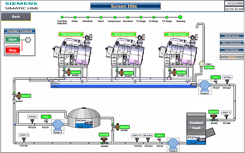
Software Development for HMI (Siemens TIA Portal WinCC)
-
IFAT, CFAT and SAT
The project was a success, completed within schedule with all the control and functional requirements achieved.
Project Title: Factory Acceptance Test (FAT) Facility Project
Client: Coldharbour Marine Ltd (CHM)
Location: Nottingham, United Kingdom
Project Status: Completed
Factory Acceptance Test (FAT) Facility Project
The FAT Facility project is a multimillion pounds project created to allow for the Factory Acceptance Testing of All Marine Inert Gas Generators ranging from 500Nm3/h(0.5MW) IGG to 6000 Nm3/h (6000MW) IGG. The facility is designed to have three testing bays Electrically and Hydraulically sized to accommodate the various sizes of IGG.
Works carried out within this project includes the following:
Liaised with Power Distribution Company, Energy Providers, Meter companies and stakeholders to install and commissioning a new 1000KVA LV Transformer for the FAT Facility.
Design and installation of MCC Panels with integrated ICA section for the Powering, Control and Motoring of every Mechanical and Electrical equipment within the facility. This MCC is also integrated with Generator interface to provide secondary power upon the failure of the local power supply.
The Electrical, Instrumentation and control designs were based around Siemens Totally Integrated Automation PLC, HMI and SCADA. The PLCs used in this project are: S7-1200, S7-1500, S7-300 and Siemens Logo.
Arc Flash calculations were carried out to determine safe working distance from equipment and recommended appropriate safety gears.